


|
|
|
MASTR Executive II Modifications and Conversions
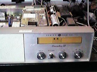
Introduction My favorite radio to convert to a repeater is the GE Mastr II Desk top station. Open the cover and you'll see that this radio can be easily 19" rack mounted. The wall mount station, if you can find one, is even better. The weakness is the power supply. I run mine at about 20 watts out with a fan on the power supply and PA heat sinks. If it's all you've got, most of these principles can be applied to a mobile version. Here's what to look out for at the hamfests. The beige color is the sign of an Exec II. Exec I's were blue/gray.
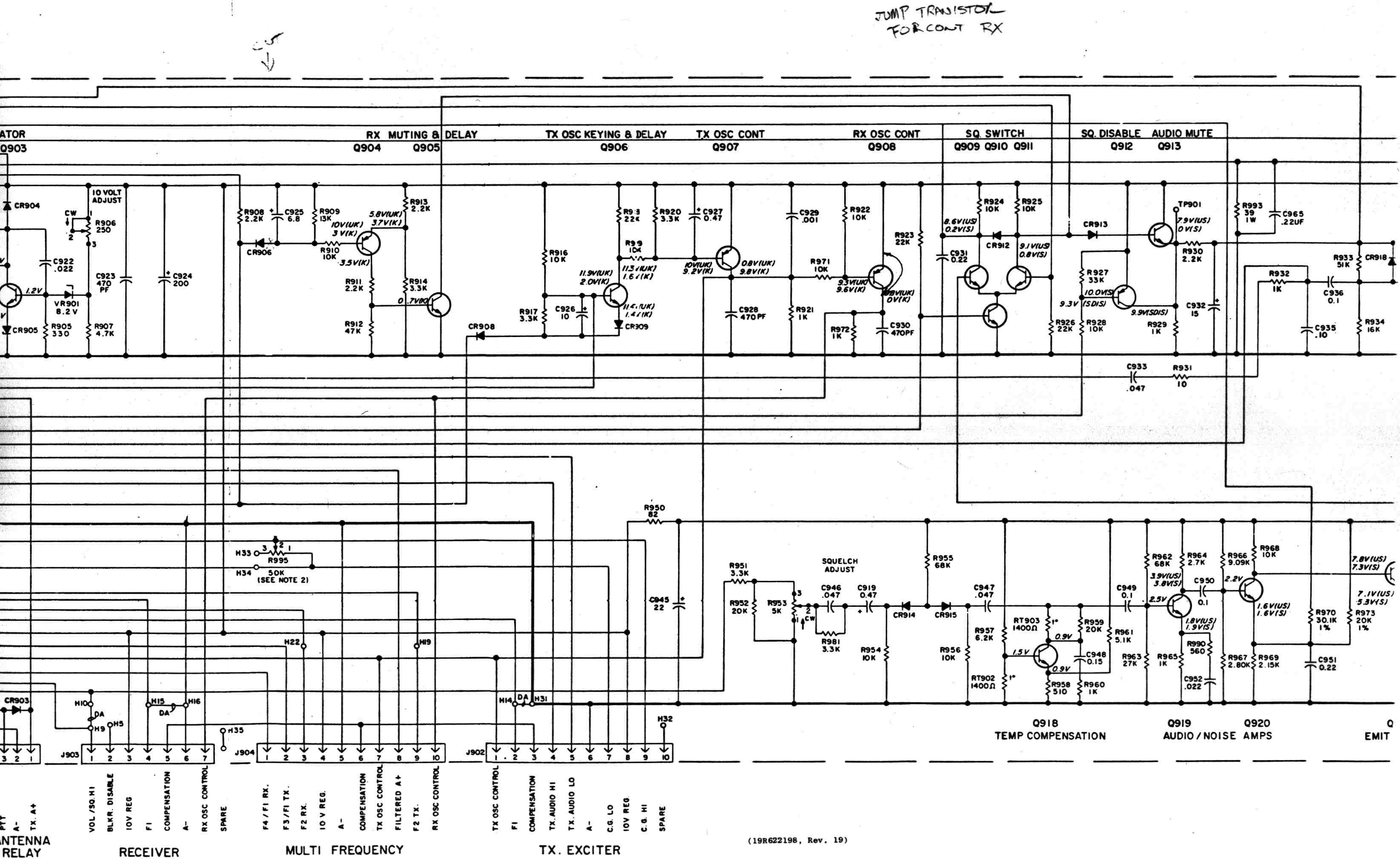
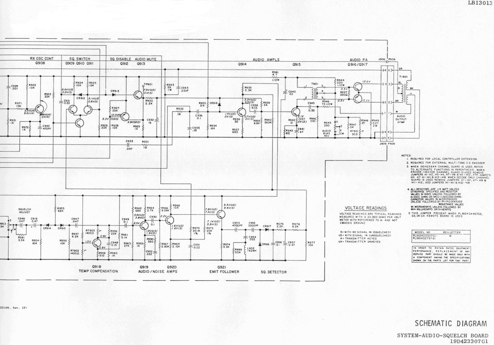
Manual Beg, borrow or steal a manual. It really does help and is worth the $20 or so you might have to pay for it. Keep an eye out at ham fests. As a last resort, try calling GE (Ericson). Years ago, when I ordered mine, it was basically free. It was under the limit they could bother billing you for. Try calling them at 1-800-528-7711. Have the combination number for your particular version handy. The manual they make up for you will have sections for each of the options that was installed when it was made. New: Here are scans of the parts layout of the base station SAS board. This is the most important board for your modification. The mobile board is similar. It's too big for the scanner, so here is the left half, and here is the right half. Even Newer: The schematic is too large to scan as one image. Click here to see the left side of the SAS board the center and and here for the right side. You'll see the jumper and cut mods hand written at the top of the center image.. This is also the base version. Mobile is similar, but not exactly the same.
Of course, this isn't the only site about GE Mastr Equipment. Here's a link to GE Technical Links. If you find any other good links, let me know. Here's a database of GE documentation. Look for your radio and you'll find the number of the manual you need to get. You'll also see the Nomenclature for your model. Here's how to tell exactly how the radio left the factory. GE uses Combination Codes to indicate all the options and configuration. But remember, since this radio is very modular, things might be very different by the time you get the radio. Look for this 10 digit code on the bottom of the base.
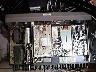
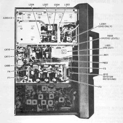
Pin-outs I have moved the pin-outs to a new page. Click here to see which pin does what in an Mastr Exec. II. Inside This is a view from above. The control panel is at the top. To the left is the power supply. PA at the bottom. All very modular and very easy to work on.
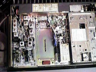
Here's a quick tour of the RF side. The exciter is on the left side. The cast section on the right is the RX front end. In the center is the RX oscillator. The dark section in the rear is the PA. The RX and TX are totally independent. This is what makes this radio a candidate for repeater operation.
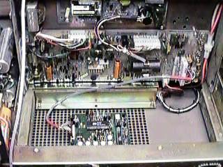
This is what you see when you lift the RF section up on its hinge. The board facing you is the SAS (System-Audio-Squelch) board, where you'll make most, if not all, your connections and mods. All of the jacks mentioned below are on this SAS board. The board in the bottom is an NHRC-3 controller. More on that on another page.
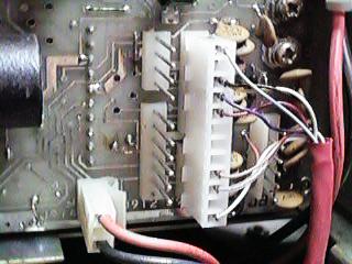
Tuning Save yourself a lot of frustration. Tune up and test the radio now, on it's old frequency. If it doesn't work now, don't bother tuning it to the ham frequency. If you try to convert it now, you'll never know if a problem is your tuning or some problem the radio had when you got it. If you need channel elements (GE calls these ICOMs) you can feel free to use a model from another band. Unlike the Mastr II line, there is only one version for temperature compensation. So far, I've been able to get both the UHF and VHF models to the ham band without component changes. If you go below 147.00 on a VHF, you might need to make some changes. Look for clear peaks. If you run out of tuning slug before you peak, then changes might be needed. Here is a diagram of the parts that need to be tuned. Repeater Conversion First of all, you have to modify the radio to not disable the receiver when the transmitter is on. This part is simple. Simply cut one side of CR906 and jump the collector and emitter of Q908. Both of these are on the System-Audio-Squelch board. See the layout and schematic available above. Run a new piece of coax from your duplexer to the receiver input. The existing output cable can be connected to the transmitter port of the duplexer. Some people modify the PA section to by-pass the TX/RX RF Relay. I don't, and I've never had one fail. The choice is yours. Controls When you pull the chassis out of the desktop case, don't worry about losing control of the radio. The volume control isn't needed, squelch is on the SAS board and the channel selection is usually done by jumper. Once I have it all tested, I just pull the one connector going to the front panel. If everything still works, your done. If you lose TX or RX, then you might need to fix the ICOMs to always on. This is best done on the SAS board. To force the TX to F1, install a jumper between H14 and H31. For the receiver, H15 and H16. Check the manual for the exact locations. Unfortunately, the boards are not marked with the component numbers. Tone The tone deck can either encode or decode, but not both at the same time. To get the tone deck to not go into encode mode, lift the white/orange/red wire on pin 3 jack 907. This means the receiver will operate in tone mode, but the transmitter will not transmit a tone. If you must transmit a tone, add another third party encoder. Pre/De-Emphasis At some point in repeater building or linking, you'll need to de-emphasize emphasized audio, or emphasize flat audio. This is simple, but it helps to know why you're doing it. Check this page at Batlabs for a simple explanation and examples of the resistor/capacitor combinations you'll need to do it. Some controllers do the de-emphasis for you with a jumper or component change. But if not, be ready to add a couple parts. Interconnections Some versions of the desktop had a board in the bottom of the chassis. This was used to connect DC remotes from other locations. The connector this board used to the SAS board is perfect for a controller. Everything you need is in J901 except 12 VDC, which you might not even need. In many cases the regulated 10V feed is plenty for your controller. J901 is actually made up of two plugs on the board, J901A and J901B. They are spaced so a single 12 pin plug will fit over both. Here's a close up of J901 with a controller already installed. The unused connector to the left of J901 is J912 for the front panel. The three pin connector with the red and black wires at the bottom of the picture is J914. This is where power (+13.8VDC) comes onto the board.
As time goes on, I'll give more information about how these radios can be used.
"Mods for converting GE Master Executive II from 37mc to 52mc"
NHRC Right now, I have documented, in detail, how to connect this model radio to two very cool, yet low cost controllers made by NHRC. The NHRC-2 is a kit, the -3 is a controller you can only buy assembled.
Need a real cheap IDer? This was in the Repeater-Builder mailing list: From: Matt Krick DCFluX@yahoo.com I've used the Radio Shack 276-1324 10 second voice storage board to ID some of my links. add a 555 timer for a pulse per minute and then timed by a 74LS192 to count down to id. An important feature of the storage module is that the REC LED signal pulses low at the end of the message, use this signal to unkey the transmitter, I have posted a schematic at http://www.egroups.com/files/Repeater-Builder/pix/ider.gif for everyone's enjoyment. Email me if you need any assistance. --Matt
Ray, KD4BBM 01/14/08 01:12 PM |
|